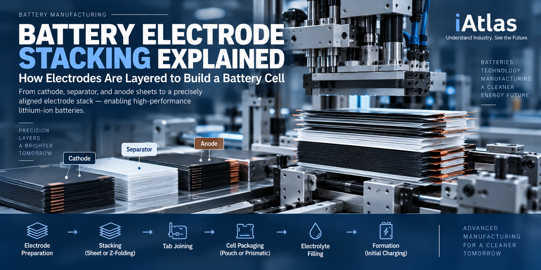
Battery Electrode Stacking Explained: How Electrodes Are Layered to Build a Battery Cell
Understanding Electrode Layering, Separator Placement, Z-Folding, Alignment, Stacking Accuracy, and Quality Control in Lithium-ion Battery Manufacturing
Category: Battery Technology
Content Type: Manufacturing
Learning Path: Battery Manufacturing
Related Industries: Electric Vehicles · Energy Storage Systems · Consumer Electronics
Last Updated: September 2026
Industry Snapshot
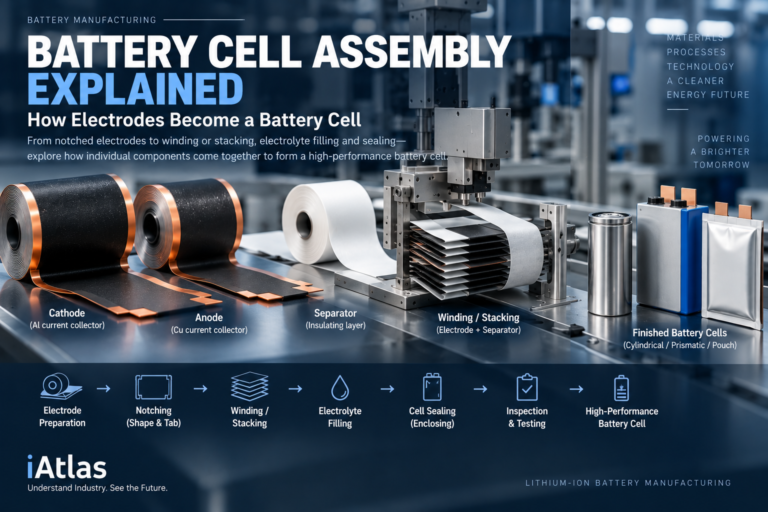
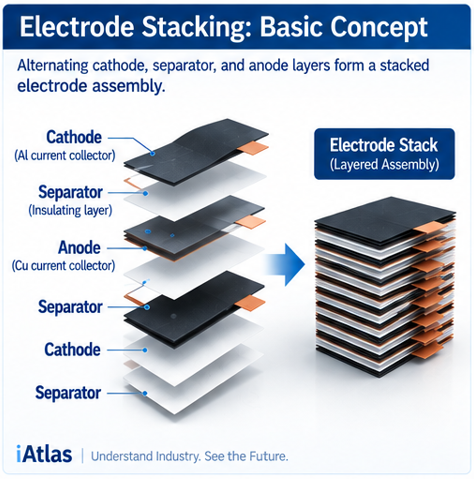
Battery electrode stacking is a cell assembly process that builds the internal electrode structure of a lithium-ion battery by arranging cathode, separator, and anode layers in a precisely controlled sequence.
Unlike winding, where continuous electrode and separator webs are rolled into a jelly roll, stacking creates a layered electrode assembly.
A simplified structure is:
Anode
↓
Separator
↓
Cathode
↓
Separator
↓
Anode
↓
Repeated Layering
↓
Electrode Stack
Stacking is particularly relevant to many prismatic and pouch cell architectures, although the exact assembly method varies by cell manufacturer and design.
The challenge is straightforward in concept but demanding in production:
Hundreds of layers may need to be positioned rapidly while maintaining precise alignment and separator coverage.
As battery cells become larger and production speeds increase, stacking equipment must combine high throughput with increasingly precise layer placement.
At a Glance
| Category | Description |
|---|---|
| Process | Electrode Stacking |
| Stage | Battery Cell Assembly |
| Input | Cathode · Anode · Separator |
| Main Function | Build multilayer electrode structure |
| Output | Electrode Stack |
| Key Methods | Sheet Stacking · Z-Folding |
| Key Controls | Alignment · Position · Separator Coverage · Layer Accuracy |
| Typical Applications | Pouch Cells · Many Prismatic Cells |
| Alternative Process | Electrode Winding |
| Next Process | Tab Joining · Housing/Pouch · Electrolyte Filling |
What Is Battery Electrode Stacking?
Battery electrode stacking is the process of arranging cathode, separator, and anode materials into a multilayer structure that forms the electrochemically active core of a battery cell.
A simplified sequence is:
Prepared Cathode Sheets
Prepared Anode Sheets
Separator
↓
Positioning
↓
Layer-by-Layer Assembly
↓
Alignment
↓
Electrode Stack
The separator remains between the positive and negative electrodes to prevent direct electrical contact while later allowing lithium ions to move through the electrolyte.
The final stack must therefore maintain both:
Electrochemical Layering
and
Electrical Isolation
throughout the entire assembly.
Where Stacking Fits in Battery Manufacturing
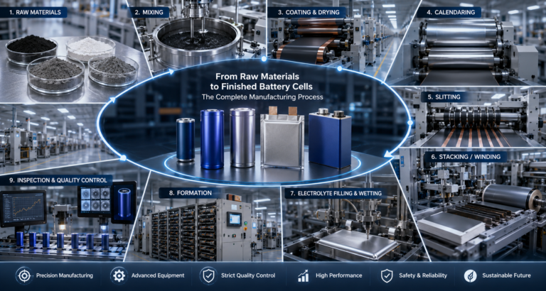
Stacking occurs after the electrodes have already passed through multiple manufacturing processes.
Electrode Manufacturing
Material Mixing
→ Slurry
→ Coating
→ Drying
→ Calendering
→ Slitting
Electrode Converting
Notching / Cutting
↓
Cell Assembly
Stacking
↓
Electrode Stack
↓
Tab Connection
↓
Cell Housing / Pouch Packaging
↓
Electrolyte Filling
↓
Sealing
↓
Formation
This means stacking quality depends heavily on the dimensional and mechanical quality established during earlier processes.
Main Components of an Electrode Stack
A stacked battery structure contains three fundamental components.
Cathode
The cathode typically consists of active material coated on an aluminum current collector.
Anode
The anode commonly consists of graphite or another anode material coated on a copper current collector.
Separator
The separator is a porous electrically insulating membrane positioned between cathode and anode layers.
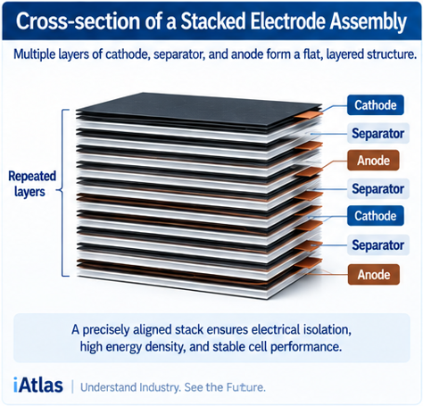
The repeated structure can be represented as:
Cathode
Separator
Anode
Separator
Cathode
Separator
Anode
…
The exact sequence at the outer layers depends on the specific cell design.
Why Electrode Alignment Matters
Stacking requires each electrode sheet to be positioned relative to the other layers.
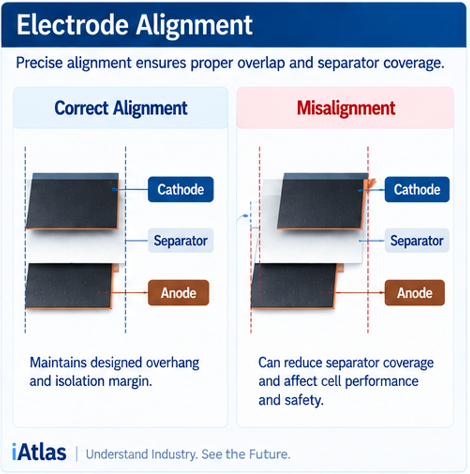
Consider a simplified top view.
Correct Alignment
Cathode
▰▰▰▰▰
Anode
▰▰▰▰▰▰
Separator
▰▰▰▰▰▰▰
The designed overlap and isolation margins are maintained.
Misalignment
Cathode
▰▰▰▰▰
Anode
▰▰▰▰▰▰
Separator
▰▰▰▰▰▰▰
A positional error can alter electrode overlap or reduce separator coverage.
Because many layers are stacked, repeated small deviations can influence the geometry of the finished cell.
Electrode Overhang
Battery cell designs commonly define specific dimensional relationships between cathode and anode active areas.
The anode may extend beyond the cathode according to the electrochemical design.
This controlled difference is commonly referred to as electrode overhang.
Stacking equipment must preserve the intended:
- Cathode position
- Anode position
- Separator margin
- Tab position
- Electrode overlap
The exact dimensions are cell-design-specific and should not be generalized across manufacturers.
Separator Placement
Separator placement is one of the most important aspects of stacking.
The separator must provide continuous electrical isolation between opposing electrodes.
Its dimensions and position are therefore designed to provide sufficient coverage around the active electrode area.
Potential problems include:
- Separator displacement
- Wrinkles
- Folding errors
- Insufficient edge coverage
- Contamination
- Mechanical damage
Because separators are thin and flexible, they require different handling characteristics from coated electrode sheets.
How Battery Electrode Stacking Works
A simplified automated stacking system can include:
Cathode Supply
Anode Supply
Separator Supply
↓
Pick & Place / Material Feeding
↓
Position Detection
↓
Layer Placement
↓
Alignment Inspection
↓
Repeated Stacking
↓
Completed Electrode Stack
High-speed systems must repeat this sequence many times while maintaining the required positional accuracy.
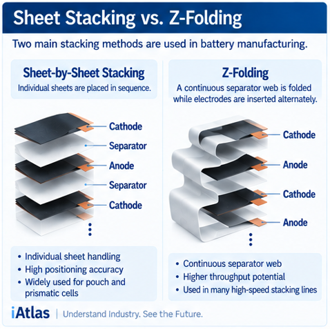
Sheet-by-Sheet Stacking
One approach uses individually cut cathode and anode sheets.
Robotic or automated handling mechanisms pick up each electrode and place it in sequence.
Conceptually:
Cathode Sheet
↓
Separator
↓
Anode Sheet
↓
Separator
↓
Repeat
The method provides direct control over individual layer placement.
However, productivity depends on how quickly electrodes can be:
- Picked
- Transported
- Positioned
- Inspected
- Released
without damaging them.
What Is Z-Folding?
Z-folding is another electrode assembly approach.
Instead of using individual separator sheets between every electrode, a continuous separator web can be folded back and forth while cathode and anode sheets are inserted alternately.
Conceptually:
Separator →
↘ Cathode
← Separator
↙ Anode
Separator →
↘ Cathode
← Separator
The resulting separator path resembles a repeated zigzag or Z-shaped folding pattern.
Why Z-Folding Is Used
Z-folding allows a continuous separator web to isolate alternating electrode sheets.
Potential advantages include:
- Continuous separator handling
- Controlled electrode isolation
- Reduced handling of individual separator sheets
- Compatibility with automated stacking equipment
However, the process introduces additional requirements for:
- Separator tension
- Folding accuracy
- Electrode insertion timing
- Layer alignment
- Fold geometry
High-speed Z-folding therefore requires coordinated motion control.
Sheet Stacking vs Z-Folding
| Characteristic | Sheet Stacking | Z-Folding |
|---|---|---|
| Separator | Individual or process-specific placement | Continuous folded web |
| Electrode Handling | Individual sheets | Individual sheets |
| Separator Motion | Intermittent | Repeated folding |
| Key Control | Sheet placement | Placement + separator folding |
| Alignment Requirement | High | High |
| Automation Potential | High | High |
| Main Challenge | Fast precise handling | Coordinated high-speed folding |
The actual production architecture can vary significantly between manufacturers.
Winding vs Stacking
Winding and stacking create the same fundamental electrochemical relationship—alternating cathode, separator, and anode—but through different manufacturing architectures.
| Winding | Stacking | |
|---|---|---|
| Structure | Wound layers | Layered sheets |
| Output | Jelly Roll | Electrode Stack |
| Material Handling | Continuous web | Sheet/layer handling |
| Typical Cells | Cylindrical + some prismatic | Pouch + many prismatic |
| Key Control | Tension & winding geometry | Placement & alignment |
| Separator Handling | Continuous winding | Sheet or folded web |
| Geometry Flexibility | Winding-dependent | High for flat cell structures |
One method is not universally better than the other.
The optimal architecture depends on cell geometry, production design, electrode dimensions, throughput targets, and equipment strategy.
Why Stacking Is Attractive for Large Flat Cells
Stacking can be particularly suitable for flat rectangular cell structures.
Because electrode sheets can be shaped before assembly, the active layers can occupy a large portion of the rectangular cell footprint.
This can make stacking attractive for certain:
- Pouch cells
- Large-format prismatic cells
- High-capacity cell designs
However, any advantage depends on the complete cell architecture rather than stacking alone.
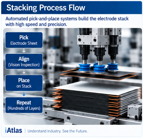
Pick-and-Place Handling
Automated stacking frequently requires rapid movement of thin electrode sheets.
Possible handling mechanisms include:
- Vacuum grippers
- Mechanical handling systems
- Robotic pick-and-place units
- High-speed linear motion systems
The system must move the electrode without causing:
- Bending
- Scratching
- Coating damage
- Edge damage
- Particle generation
This becomes increasingly difficult as electrodes become larger and thinner.
Why Electrode Handling Is Challenging
Battery electrodes are not simple metal sheets.
They consist of brittle or semi-brittle composite coatings attached to thin metallic current collectors.
Handling forces can therefore affect:
Coating Integrity
Electrode Flatness
Edge Quality
Particle Generation
Upstream electrode mechanical properties established during coating, drying, and calendering can influence stacking behavior.
Stacking Speed and Productivity
A cell may contain many individual electrode layers.
This creates a fundamental productivity challenge.
If each layer requires:
Pick
→ Move
→ Align
→ Place
→ Inspect
then even small reductions in cycle time can significantly affect production throughput.
Modern stacking equipment therefore aims to increase layers per minute while maintaining positioning accuracy.
Accuracy vs Throughput
Stacking demonstrates a recurring battery-manufacturing trade-off:
Higher Speed
can make
Precision Control More Difficult
Equipment must therefore optimize:
Throughput
Positioning Accuracy
Gentle Material Handling
Defect Detection
The fastest stacking system is not useful if increased speed causes unacceptable misalignment or damage.
Stack Height
As layers accumulate, the electrode stack becomes thicker.
The equipment must account for the changing stack height during assembly.
Conceptually:
Layer Count ↑
↓
Stack Height ↑
↓
Placement Position Changes
Without compensation, the placement conditions of later layers could differ from earlier layers.
Motion systems therefore need accurate vertical positioning throughout the stacking cycle.
Stack Compression
After or during stacking, the electrode assembly may require controlled handling or compression to stabilize its geometry.
Excessive force can damage:
- Electrode coatings
- Separator
- Electrode edges
Insufficient control can allow layers to shift.
Compression strategy therefore depends on the cell and assembly design.
Tab Alignment
Notched electrodes contain current-collection regions that eventually connect to the cell terminals.
During stacking, these regions must be positioned according to the intended electrical architecture.
Repeated electrode placement creates groups of current-collector features that can later be joined.
Poor positioning can complicate:
- Tab joining
- Welding
- Terminal connection
- Cell packaging
Stacking accuracy therefore affects downstream electrical assembly.
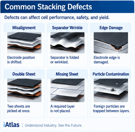
Common Electrode Stacking Defects
Several defects can occur during stacking.
Electrode Misalignment
Cathode and anode sheets are displaced relative to their intended positions.
Separator Misalignment
Separator coverage becomes insufficient or inconsistent.
Separator Wrinkles
The thin separator folds or deforms during handling.
Electrode Damage
Coatings or current collectors are damaged during pick-and-place.
Edge Damage
Electrode edges become bent, chipped, or contaminated.
Particle Contamination
Loose material becomes trapped between layers.
Tab Position Error
Current-collection features fail to align correctly.
Double Sheet
Two electrode sheets may accidentally be handled together.
Missing Sheet
A required electrode layer is not placed.
These errors can propagate into the finished cell if they are not detected during assembly.
Why Particles Matter During Stacking
Stacking directly creates the layered internal structure of the battery.
A foreign particle introduced during this stage can potentially become trapped between:
- Electrode and separator
- Adjacent separator surfaces
- Electrode layers
Conductive metallic particles are particularly undesirable.
This makes cleanliness and contamination control essential around stacking equipment.
Quality Control During Stacking
Modern stacking lines can monitor multiple parameters.
Electrode Position
Confirms cathode and anode placement.
Separator Position
Checks isolation coverage.
Electrode Dimensions
Verifies incoming sheet geometry.
Tab Position
Confirms current-collection alignment.
Layer Count
Ensures the correct number of electrodes has been assembled.
Surface Defects
Detects visible damage or contamination.
Stack Geometry
Checks the final dimensions of the assembled electrode stack.
Machine Vision in Electrode Stacking
Machine vision is particularly valuable because stacking involves repeated geometric placement.
A simplified system is:
Electrode Sheet
↓
Camera
↓
Edge / Feature Detection
↓
Position Calculation
↓
Placement Correction
↓
Stacking
Cameras can potentially identify electrode edges, tabs, separator boundaries, and other reference features.
The measurement data can then be used for closed-loop alignment control.
Inline Inspection
Inspection does not need to occur only after the stack is complete.
High-speed imaging can be integrated into the assembly cycle.
Conceptually:
Pick
↓
Inspect
↓
Align
↓
Place
↓
Verify
↓
Next Layer
This can allow errors to be detected closer to the point where they occur.
From Electrode Stack to Cell Packaging
Once stacking is complete, the electrode assembly proceeds to additional cell-assembly operations.
A simplified pouch-cell sequence is:
Electrode Stack
↓
Tab Joining
↓
Pouch Packaging
↓
Electrolyte Filling
↓
Initial Sealing
↓
Formation
↓
Degassing
↓
Final Sealing
Prismatic-cell sequences can differ depending on housing and assembly architecture.
Electrolyte Wetting in Stacked Cells
After electrolyte filling, liquid electrolyte must penetrate throughout the porous electrode stack.
It must wet:
- Cathode pores
- Anode pores
- Separator pores
- Interfaces between layers
Stacking geometry can therefore influence the pathways available for electrolyte distribution.
This connects stacking with earlier manufacturing variables such as:
- Electrode thickness
- Porosity
- Calendering conditions
and later processes such as:
- Electrolyte filling
- Wetting
- Formation
Why Stacking Matters to Battery Performance
Stacking determines the physical relationship between many active electrode layers.
Poor assembly can influence:
- Electrode overlap
- Separator coverage
- Electrical isolation
- Current-collection geometry
- Mechanical uniformity
- Cell dimensions
- Electrolyte distribution
- Reliability
The process therefore directly connects mechanical manufacturing precision with electrochemical cell quality.
Emerging Electrode Stacking Technologies
Stacking equipment continues to evolve toward higher speed and greater automation.
High-Speed Stacking
Equipment manufacturers are increasing layer placement rates while maintaining positioning accuracy.
Advanced Motion Control
Servo and linear-motor systems enable faster and more precise electrode movement.
Continuous Z-Folding
High-speed separator folding systems can increase assembly throughput.
Machine Vision
High-resolution cameras monitor electrode and separator position.
Closed-Loop Alignment
Measured position errors can be corrected automatically before placement.
Automated Defect Classification
Vision algorithms can classify stacking defects.
Digital Traceability
Layer-placement and inspection data can be linked to production records.
Predictive Maintenance
Motion, vacuum, sensor, and equipment data can be used to identify performance degradation.
The direction is toward increasingly adaptive and self-monitoring cell assembly equipment.
iAtlas Insight
Electrode stacking highlights one of the central challenges of modern battery manufacturing:
A large battery cell is built through the repeated control of very small positional errors.
A single electrode sheet may appear simple.
But when many layers are assembled, small deviations can accumulate or repeat throughout the cell.
This creates a manufacturing equation:
Large Cell Format
Thin Materials
Many Repeated Layers
High Production Speed
=
Demand for Extreme Process Control
As battery factories move toward larger cells and greater automation, stacking equipment increasingly combines:
Precision Motion
Machine Vision
Material Handling
Inline Inspection
Process Data
The stacking machine is therefore evolving from a mechanical assembly device into an integrated precision cell-building platform.
Did You Know?
- Stacking builds the battery’s active core layer by layer rather than winding it into a jelly roll.
- Many pouch and prismatic battery designs use stacked electrode structures.
- Z-folding uses a continuous separator web folded between alternating electrodes.
- Separator placement is as important as electrode alignment.
- Electrode overhang is intentionally designed and must be maintained during stacking.
- High-speed stacking requires extremely fast but gentle handling of thin electrode sheets.
- Machine vision can measure electrode position before each layer is placed.
- Upstream notching accuracy directly influences stacking and tab alignment.
FAQ
What is battery electrode stacking?
Battery electrode stacking is a cell assembly process that arranges cathode, separator, and anode materials into a multilayer electrode structure.
What is the difference between winding and stacking?
Winding forms a continuous wound jelly roll, while stacking builds the electrode assembly using repeated layers or sheets.
What is Z-folding?
Z-folding uses a continuous separator web folded back and forth while cathode and anode sheets are inserted alternately.
Which battery cells use stacking?
Stacking is widely associated with pouch cells and many prismatic-cell designs, although the exact architecture varies by manufacturer.
Why is electrode alignment important?
Misalignment can change electrode overlap, separator coverage, tab position, and the intended geometry of the cell.
Why is separator alignment critical?
The separator electrically isolates the cathode and anode. Its designed coverage must be maintained throughout the stack.
What defects can occur during stacking?
Typical concerns include electrode misalignment, separator wrinkles, edge damage, particles, missing or double sheets, and incorrect tab positioning.
What comes after stacking?
The completed electrode stack proceeds to downstream operations such as tab joining, packaging or housing, electrolyte filling, and sealing.
Battery Manufacturing Learning Path
Overview
Electrode Manufacturing
Cell Assembly
- Battery Cell Assembly
- Battery Electrode Notching
- Battery Electrode Winding
- Battery Electrode Stacking (Current)
- Electrolyte Filling
- Cell Sealing
Cell Finishing
- Formation
- Aging
- Degassing
- Battery Cell Testing & Grading
System Assembly
- Battery Module Assembly
- Battery Pack Assembly
Explore More
Cell Assembly
- Battery Cell Assembly
- Battery Electrode Notching
- Battery Electrode Winding
- Battery Electrode Stacking (Current)
- Electrolyte Filling
- Cell Sealing
Electrode Manufacturing
- Slitting
- Calendering
Battery Components
- Cathode
- Anode
- Separator
- Battery Cell
References
Recommended primary-source areas for this article:
- Procedia CIRP — Simulation of the Stacking Process in Battery Cell Manufacturing
- Energy Technology — Quality Assurance for Flexible Stack Assembly of Lithium-Ion Cells
- Procedia CIRP — Enhanced Deposition Accuracy for Battery Electrodes in a Novel High-Speed Stacking Process
- KIT — Quality Assurance for Flexible Stack Assembly of Lithium-Ion Cells
About iAtlas
iAtlas is an independent publication covering batteries, semiconductors, OLED, advanced materials, AI, and global industrial trends.
We transform complex industrial developments into clear, reliable, and easy-to-understand insights.
Whether you’re following today’s industry news or building long-term expertise, iAtlas helps you understand not only what happened, but why it matters.
Technology creates change.
Insight creates opportunity.
— iAtlas