
Battery Module Assembly Explained: How Individual Cells Become a Battery Module
Understanding Cell Sorting, Mechanical Integration, Busbar Welding, Thermal Management, Electrical Connections, and Quality Control in Battery Module Manufacturing
Topic: Processes
Process Stage: System Assembly
Content Type: Manufacturing
Learning Path: Battery Manufacturing
Related Industries: Electric Vehicles · Energy Storage Systems · Industrial Batteries
Last Updated: November 2026
Industry Snapshot
A lithium-ion battery cell is the fundamental electrochemical unit that stores and releases electrical energy.
However, a single cell generally cannot provide the voltage, capacity, power, or mechanical integration required by large battery systems.
To create larger energy storage systems, multiple cells are electrically connected and mechanically integrated.
In modular battery architectures, this process produces a battery module.
Battery module assembly is the manufacturing stage that transforms tested and classified battery cells into a mechanically supported, electrically connected, and thermally managed unit.
The process may involve:
- Cell sorting and matching
- Cell positioning and stacking
- Mechanical fixation and compression
- Busbar installation and joining
- Thermal management integration
- Voltage and temperature sensing
- Electrical insulation
- Module-level inspection and testing
A simplified manufacturing sequence is:
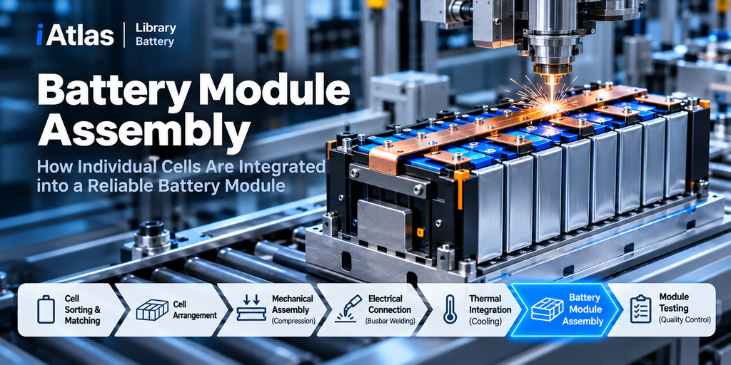
Tested Battery Cells → Cell Arrangement → Mechanical Assembly → Electrical Interconnection → Thermal Integration → Module Testing
The exact sequence depends on cell format, module architecture, and production equipment.
Battery module assembly is where individual cell performance becomes the performance of an integrated electrical and mechanical system.
At a Glance
| Category | Description |
|---|---|
| Process | Battery Module Assembly |
| Manufacturing Stage | System Assembly |
| Primary Purpose | Integrate multiple cells into a functional battery module |
| Main Inputs | Tested and classified lithium-ion cells |
| Key Components | Cells, busbars, frames, insulation, cooling components, sensors |
| Main Operations | Cell placement, fixation, joining, electrical connection, inspection |
| Common Joining Methods | Laser welding, ultrasonic welding, resistance welding, mechanical fastening |
| Critical Variables | Cell alignment, contact resistance, weld quality, compression, insulation |
| Quality Requirements | Electrical continuity, mechanical stability, insulation, traceability |
| Downstream Process | Battery Pack Assembly |
1. What Is Battery Module Assembly?
Battery module assembly is the manufacturing process of combining multiple battery cells into a mechanically and electrically integrated unit.
A typical module includes battery cells, structural supports, electrical connections, insulation, and interfaces for monitoring and thermal management.
Depending on the design, the module may also include cooling plates, temperature sensors, voltage sensing connections, and other components.
Cell vs Module vs Pack
| Level | Description | Main Function |
|---|---|---|
| Battery Cell | Individual electrochemical unit | Stores and releases energy |
| Battery Module | Group of electrically connected cells with supporting structures | Provides a manageable electrical and mechanical assembly |
| Battery Pack | Integrated system containing modules or directly integrated cells | Provides application-level energy storage and protection |
Not every modern battery pack uses conventional modules.
Some manufacturers use Cell-to-Pack (CTP) or other module-reduced architectures that integrate cells more directly into the pack structure.
This article focuses on conventional modular battery manufacturing.
2. Where Module Assembly Fits in Battery Manufacturing
Electrode Manufacturing
Material Mixing → Slurry → Coating → Drying → Calendering → Slitting
Cell Assembly
Notching → Winding / Stacking → Electrolyte Filling → Sealing
Cell Finishing
Formation → Aging → Degassing → Testing & Grading
System Assembly
Battery Module Assembly (Current) → Battery Pack Assembly
Module assembly therefore connects cell-level manufacturing to system-level battery production.
The quality of the incoming cells is important, but module manufacturing introduces additional electrical, mechanical, and thermal requirements.

3. Step 1 — Cell Sorting and Matching
The first stage is selecting cells suitable for integration into the same module.
Cells are typically evaluated using data from previous manufacturing tests.
Relevant characteristics may include:
- Measured capacity
- Internal resistance
- Open-circuit voltage
- State of charge
- Self-discharge characteristics
- Dimensions and physical condition
Why Matching Matters
Cells connected in series carry the same current.
If one cell has significantly lower capacity, it may reach its voltage limit earlier than other cells and constrain the usable capacity of the series group.
Resistance differences can also affect voltage behavior and heat generation.
Therefore, manufacturers aim to reduce undesirable variation between cells assembled into the same electrical group.
Cell Matching Workflow
Cell Identification → Test Data Verification → Matching Criteria → Cell Group Selection → Module Assembly
Matching criteria are product-specific.
A universal capacity or resistance matching tolerance does not apply to every battery chemistry or module design.
4. Step 2 — Cell Arrangement and Positioning
After matching, cells are arranged according to the module’s electrical and mechanical design.
The arrangement depends heavily on cell format.
Cylindrical Cells
Cylindrical cells are commonly positioned in holders or structural fixtures.
Important considerations include:
- Cell spacing
- Orientation
- Terminal accessibility
- Cooling pathways
- Mechanical support
Prismatic Cells
Prismatic cells may be arranged in rows or stacks with controlled compression and structural support.
Important considerations include:
- Cell orientation
- Stack alignment
- Swelling allowance
- Contact pressure
- Cooling surface integration
Pouch Cells
Pouch cells often require carefully controlled mechanical support and compression.
Important considerations include:
- Cell stacking accuracy
- Pressure distribution
- Tab alignment
- Pouch protection
- Thermal contact
The objective is to position cells consistently while avoiding damage to terminals, packaging, and internal structures.

5. Step 3 — Mechanical Fixation and Compression
Battery cells must remain securely positioned during handling, transportation, and operation.
Mechanical integration may involve:
- Module frames
- End plates
- Side plates
- Cell holders
- Compression elements
- Adhesives
- Structural fasteners
Why Compression Matters
Certain cell formats, especially pouch and prismatic designs, may require controlled compression or mechanical restraint.
Cells can undergo dimensional changes during charging, discharging, and aging.
The module structure must accommodate these changes without creating excessive stress.
Too little mechanical support may allow undesirable movement or deformation.
Excessive compression can also damage cells or alter their mechanical and electrochemical behavior.
Therefore, compression requirements must be established for the particular cell design.
Mechanical Design Objectives
Secure Positioning + Controlled Compression + Vibration Resistance + Thermal Accommodation
These requirements must be balanced rather than optimized independently.
6. Step 4 — Busbar Installation and Electrical Connection
Busbars provide electrical connections between battery cells.
They are typically made from conductive materials such as copper or aluminum, depending on the design.
Busbars connect cells in series, parallel, or combinations of both.
Series Connection
In a series connection, cell voltages add together.
\[ V_{\text{module}}=\sum_{i=1}^{n}V_i \]
For example, 12 cells with a nominal voltage of 3.7 V connected in series provide:
\[ 12\times3.7=44.4\text{ V} \]
The module’s nominal voltage is approximately 44.4 V.
Parallel Connection
In a parallel connection, cell capacities add under appropriate matching and operating assumptions.
\[ Q_{\text{module}}=\sum_{i=1}^{n}Q_i \]
For example, four 50 Ah cells connected in parallel provide a nominal combined capacity of:
\[ 4\times50=200\text{ Ah} \]
Series-Parallel Configuration
A module may combine both configurations.
For example, a 12S4P arrangement means:
- 12 cell groups connected in series
- 4 cells connected in parallel within each group
- 48 cells in total
For the illustrative 3.7 V, 50 Ah cells:
| Parameter | Nominal value |
|---|---|
| Module Voltage | 44.4 V |
| Module Capacity | 200 Ah |
| Module Energy | 8.88 kWh |
The energy estimate is:
\[ E_{\text{nominal}}=\frac{V_{\text{nominal}}\times Q_{\text{nominal}}}{1000} \]
Actual usable energy depends on operating limits and other system conditions.

7. Step 5 — Busbar Welding and Joining
Electrical connections must provide low resistance, mechanical reliability, and long-term stability.
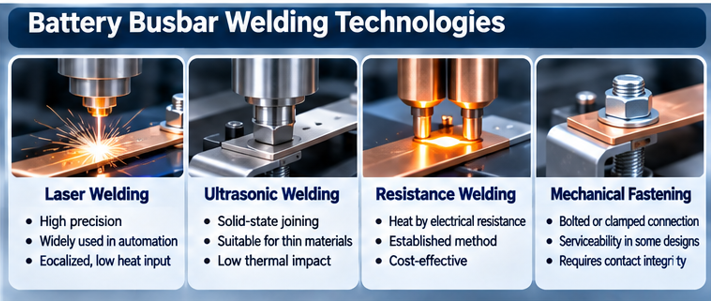
Common joining technologies include laser welding, ultrasonic welding, resistance welding, and mechanical fastening.
Laser Welding
Laser welding uses concentrated optical energy to join conductive components.
It is widely used in automated battery manufacturing because it can provide precise, localized joining.
Important process variables include laser power, welding speed, focus, joint geometry, and material properties.
Ultrasonic Welding
Ultrasonic welding uses high-frequency mechanical vibration under pressure to create a solid-state joint.
It can be suitable for certain thin conductive materials and tab connections.
Resistance Welding
Resistance welding generates heat through electrical resistance at the joint interface.
Its suitability depends on material properties, thickness, and connection design.
Mechanical Fastening
Bolted or other mechanically fastened connections may be used where the design permits.
They require appropriate control of contact surfaces, clamping force, and long-term joint integrity.
Joining Method Comparison
| Method | Main Advantage | Main Consideration |
|---|---|---|
| Laser Welding | Precision and automation potential | Joint design, reflectivity, process control |
| Ultrasonic Welding | Solid-state joining | Material thickness and vibration control |
| Resistance Welding | Established electrical joining method | Heat generation and electrode contact |
| Mechanical Fastening | Serviceability in suitable designs | Contact resistance and loosening risk |
No single joining technology is optimal for every cell and module design.
8. Why Electrical Connection Quality Matters
Poor electrical connections can create local resistance and heat generation.
The approximate resistive heating relationship is:
\[ P=I^2R \]
Where:
- \(P\) = heat generated (W)
- \(I\) = current (A)
- \(R\) = electrical resistance (Ω)
Example
Consider a connection carrying 100 A.
If the connection resistance is 0.1 mΩ:
\[ P=100^2\times0.0001=1\text{ W} \]
If the resistance increases to 1 mΩ:
\[ P=100^2\times0.001=10\text{ W} \]
Illustrative connection heat generation
0 W3 W6 W9 W12 W0.1 mΩ0.5 mΩ1.0 mΩ
Calculated using P = I²R at 100 A. Illustrative values.
This illustrates why relatively small increases in connection resistance can become important at high current.
Actual joint performance also depends on temperature, current profile, geometry, and heat dissipation.
9. Step 6 — Thermal Management Integration
Battery modules generate heat during charging and discharging.
Thermal management helps maintain suitable operating temperatures and reduce temperature differences between cells.
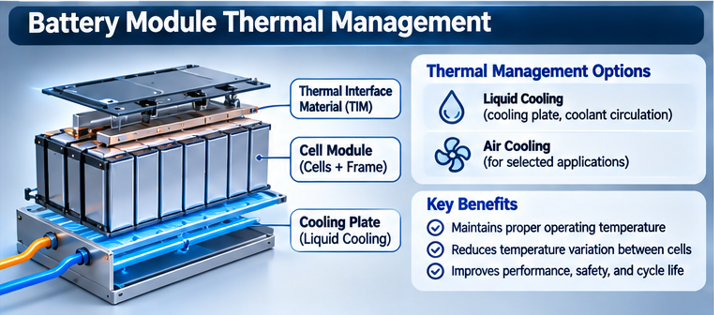
Depending on the design, module assembly may integrate:
- Cooling plates
- Thermal interface materials
- Heat spreaders
- Airflow channels
- Cooling manifolds
- Temperature sensors
Liquid Cooling
Liquid-cooled modules may use cooling plates or channels connected to a thermal management system.
Air Cooling
Some designs use forced or natural airflow around cells.
Thermal Interface Materials
Thermal interface materials help reduce thermal contact resistance between cells and cooling components.
Why Temperature Uniformity Matters
Cells operating at different temperatures may experience different resistance, capacity, and degradation behavior.
Therefore, module design must consider both average operating temperature and temperature distribution.
10. Step 7 — Electrical Insulation and Protection
Battery modules must prevent unintended electrical contact between conductive components.
Insulation measures may include:
- Insulating films
- Cell spacers
- Protective covers
- Busbar insulation
- Dielectric barriers
- Terminal protection
Insulation Coordination
The required insulation depends on module voltage, electrical architecture, environmental conditions, and applicable safety requirements.
Mechanical Protection
Insulation materials must also withstand assembly forces, vibration, temperature changes, and expected service conditions.
Manufacturing Risks
Potential issues include damaged insulation, incorrect placement, exposed conductive parts, and contamination.
Inspection is therefore essential before module-level electrical testing.
11. Step 8 — Voltage and Temperature Sensing
A battery management system requires information about the condition of the cells.
Module assembly may include voltage sensing connections, temperature sensors, and wiring harnesses.
Voltage Monitoring
Voltage sensing allows the system to monitor individual cells or cell groups, depending on the architecture.
Temperature Monitoring
Temperature sensors help identify operating conditions and support thermal protection.
Sensing Harness Integration
Harnesses must be routed and secured to avoid damage, incorrect connections, and unintended contact.
Cell Monitoring Units
Some modular systems include cell monitoring electronics within or near the module.
Other systems integrate monitoring differently at pack level.
The exact configuration depends on the battery management architecture.
12. Battery Module Assembly Equipment
Industrial module assembly lines integrate multiple automated and semi-automated operations.
Typical equipment may include:
| Equipment | Main Function |
|---|---|
| Cell Sorting System | Selects cells using test and matching data |
| Cell Placement Robot | Positions cells accurately |
| Stacking / Compression Equipment | Applies controlled mechanical assembly forces |
| Adhesive Dispensing System | Applies structural or thermal materials |
| Laser Welding System | Joins electrical conductors |
| Busbar Placement System | Positions electrical interconnections |
| Vision Inspection System | Checks alignment and visible defects |
| Electrical Testing Station | Measures continuity and other characteristics |
| Leak Testing System | Checks applicable cooling circuits |
| Traceability System | Records process and inspection data |
The equipment configuration depends on cell format and module design.
A cylindrical-cell module line may differ significantly from a prismatic- or pouch-cell module line.
13. Critical Manufacturing Parameters
Battery module assembly requires precise control of mechanical and electrical variables.
| Parameter | Why It Matters |
|---|---|
| Cell Position Accuracy | Ensures consistent mechanical and electrical integration |
| Cell Compression | Controls mechanical loading |
| Weld Energy and Geometry | Influences joint quality |
| Contact Resistance | Affects electrical losses and heating |
| Adhesive Application | Influences structural or thermal performance |
| Cooling Interface Quality | Affects heat transfer |
| Insulation Integrity | Prevents unintended electrical contact |
| Sensor Placement | Influences monitoring reliability |
| Component Traceability | Supports quality investigations |
A defect in one assembly operation may affect the performance or reliability of the entire module.
14. Common Battery Module Assembly Defects
| Defect | Possible Cause | Potential Impact |
|---|---|---|
| Cell Misalignment | Incorrect positioning | Mechanical stress or connection problems |
| Weak Weld | Inadequate joining conditions | High resistance or connection failure |
| Excessive Compression | Incorrect assembly force | Cell damage |
| Insulation Damage | Handling or assembly error | Electrical fault risk |
| Poor Thermal Contact | Inconsistent interface material | Uneven cooling |
| Incorrect Wiring | Harness assembly error | Monitoring malfunction |
| Loose Connection | Improper fastening | Heating or electrical interruption |
| Cooling Circuit Leakage | Defective sealing or joining | Loss of cooling performance |
These defects may require different inspection and testing methods.
A single electrical measurement cannot identify every mechanical or thermal defect.
15. Module-Level Quality Control and Testing
After assembly, the module undergoes defined inspections and tests.
Visual Inspection
Checks cell alignment, component installation, insulation, and visible joining defects.
Electrical Continuity
Verifies that the intended electrical connections are present.
Voltage Measurement
Confirms that the module or cell-group voltages are consistent with the intended electrical configuration.
Connection Resistance
Evaluates electrical interconnection quality where applicable.
Insulation Testing
Checks electrical isolation according to the module’s voltage class and applicable test requirements.
Cooling Circuit Testing
For liquid-cooled designs, leak or pressure testing may be required.
Sensor Verification
Confirms voltage and temperature sensing connections.
Traceability Verification
Links the module identification number to its cells, components, and manufacturing records.
The exact tests and limits must be defined by the product design and applicable quality requirements.
16. Battery Module Assembly and Automation
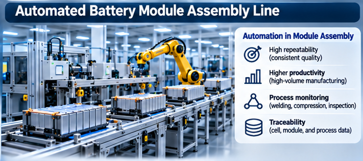
Modern battery module production increasingly relies on automated handling, joining, and inspection.
A simplified automated line can be represented as:
Cell Loading
↓
Cell Identification and Matching
↓
Cell Arrangement
↓
Mechanical Fixation
↓
Busbar Joining
↓
Thermal and Electrical Integration
↓
Inspection and Testing
↓
Completed Battery Module
Automation offers several potential advantages.
Repeatability
Robotic positioning and controlled joining can reduce process variation.
Traceability
Manufacturing data can be recorded for individual cells and modules.
Productivity
Automated operations can support high-volume production.
Quality Monitoring
Vision systems, electrical measurements, and process sensors can detect certain assembly abnormalities.
However, automation does not eliminate the need for process validation, equipment maintenance, and quality-control procedures.
17. Module Assembly vs Cell-to-Pack Manufacturing
Conventional battery manufacturing often follows:
Cell → Module → Pack
However, newer architectures can reduce or eliminate the conventional module stage.
Conventional Module-Based Architecture
Cells are assembled into modules before integration into a battery pack.
Potential advantages include modular handling, standardized interfaces, and serviceability in suitable designs.
Cell-to-Pack (CTP)
Cells are integrated more directly into the pack structure.
Potential advantages include reduced intermediate components and improved packaging efficiency.
Cell-to-Chassis / Cell-to-Body
Certain designs integrate battery structural functions more closely with the vehicle body or chassis.
These approaches create different manufacturing requirements.
They can change:
- Cell handling
- Structural integration
- Cooling design
- Assembly automation
- Inspection procedures
- Repairability
The trend toward module-reduced architectures does not make module assembly irrelevant.
Conventional modular designs remain important across many battery applications, including EV, ESS, and industrial systems.
iAtlas Insight
Battery module assembly is a critical transition from electrochemical manufacturing to systems engineering.
At the cell level, manufacturers focus on materials, electrochemical performance, and individual cell quality.
At the module level, additional requirements become equally important.
These include:
Electrical Interconnection
Mechanical Stability
Thermal Management
Insulation and Protection
Manufacturing Repeatability
The relationship can be summarized as:
Cell Quality
↓
Cell Matching
↓
Mechanical and Electrical Integration
↓
Thermal and Safety Engineering
↓
Module Performance and Reliability
One important implication is that high-quality cells do not automatically guarantee a high-quality module.
A poor weld, inadequate cooling interface, damaged insulation layer, or incorrect sensing connection can compromise an otherwise acceptable group of cells.
For manufacturers, module assembly quality depends on integrating several disciplines:
Battery Engineering + Precision Automation + Joining Technology + Thermal Design + Quality Control
As battery architectures evolve, manufacturers must adapt assembly equipment to different cell formats and integration strategies.
The long-term opportunity is not only faster assembly.
It is the development of manufacturing systems capable of producing consistent electrical, mechanical, and thermal performance at scale.
Battery module manufacturing converts cell-level quality into system-level reliability.
Did You Know?
- A battery module can contain cells connected in series, parallel, or both.
- Cell matching helps reduce performance variation within a module.
- Busbar resistance can become an important source of heat at high current.
- Laser welding is widely used for automated electrical joining.
- Pouch and prismatic cells may require controlled mechanical compression.
- Module cooling design affects both average temperature and temperature uniformity.
- High-quality cells can still form a defective module if assembly quality is poor.
- Some modern battery packs eliminate conventional modules through Cell-to-Pack architectures.
- Module-level testing evaluates different risks from cell-level testing.
FAQ
What is battery module assembly?
Battery module assembly is the manufacturing process of integrating multiple battery cells into a mechanically supported, electrically connected, and thermally managed unit.
What is the difference between a battery cell and a battery module?
A battery cell is an individual electrochemical energy-storage unit. A module combines multiple cells with supporting electrical and mechanical components.
Why are battery cells matched before module assembly?
Matching helps reduce differences in capacity, resistance, voltage, and other relevant characteristics between cells operating together.
What is a battery busbar?
A busbar is an electrical conductor used to connect battery cells or cell groups.
How are battery cells connected in a module?
Cells can be connected in series, parallel, or combinations of both using welded or mechanically fastened electrical connections.
Why is laser welding used in battery module manufacturing?
Laser welding offers precise, localized joining and can be integrated into automated production systems.
Why is thermal management important in battery modules?
Thermal management helps control cell temperatures and reduce temperature differences that can affect performance, reliability, and degradation.
Do all battery packs contain modules?
No. Some Cell-to-Pack and other module-reduced designs integrate cells directly into larger pack structures.
What comes after battery module assembly?
In a conventional modular manufacturing process, the next stage is Battery Pack Assembly.
Battery Manufacturing Learning Path
Overview
– Battery Manufacturing Process
Electrode Manufacturing
Cell Assembly
- Battery Cell Assembly
- Battery Electrode Notching
- Battery Electrode Winding
- Battery Electrode Stacking
- Battery Electrolyte Filling
- Battery Cell Sealing
Cell Finishing
System Assembly
- Battery Module Assembly (Current)
- Battery Pack Assembly — Next
Explore More
System Assembly
- Battery Module Assembly (Current)
- Battery Pack Assembly
Battery Fundamentals
- Battery Cell
- Battery Module
- Battery Pack
- Battery Management System (BMS)
- Battery Thermal Management System (BTMS)
Related Technical Concepts
- Battery Cell Matching
- Busbar Welding
- Cell-to-Pack (CTP)
- Battery Thermal Management
- Electrical Insulation
- Battery Module Testing
References
1. VDMA / PEM RWTH Aachen — Production Process of a Lithium-Ion Battery Cell (2026)
Manufacturing reference for lithium-ion battery cell production and quality-control processes. Useful background for upstream cell manufacturing; not a dedicated module assembly guide.
2. U.S. Department of Energy — Vehicle Technologies Office
Research programs covering batteries, electric vehicle technologies, and energy-storage systems.
3. Fraunhofer Institute for Manufacturing Technology and Advanced Materials IFAM
Research organization working on materials, joining technologies, and manufacturing processes relevant to battery assembly.
4. IEC 62619 — Safety Requirements for Secondary Lithium Cells and Batteries for Industrial Applications
International safety standard relevant to applicable industrial lithium battery systems.
ℹ️ About iAtlas
iAtlas is an independent publication covering batteries, semiconductors, OLED, advanced materials, AI, and global industrial trends.
We transform complex industrial developments into clear, reliable, and easy-to-understand insights.
Whether you’re following today’s industry news or building long-term expertise, iAtlas helps you understand not only what happened, but why it matters.
Technology creates change.
Insight creates opportunity.
— iAtlas