Motion Explained: How Objects Move in Engineering
⚙️ Mechanics & Motion #2 | Motion → Position, Speed, Velocity & Acceleration
What is motion in engineering?
Motion describes how the position of an object changes over time.
It may sound simple, but motion is one of the foundations of mechanical engineering. Machines move, robots accelerate, conveyors transport materials, motors rotate shafts, and vehicles change speed and direction.
To understand any of these systems, we first need to understand how engineers describe motion.
In simple terms:
Motion is the change in position of an object over time.
But engineering goes further than simply asking whether something moves.
Engineers also ask:
- How far did it move?
- In which direction?
- How fast did it move?
- Did its speed change?
- How quickly did it accelerate?
- Was the motion linear or rotational?
These questions form the basis of kinematics, the study of motion without initially focusing on the forces that cause it.
What Is Motion in Engineering?
In engineering, motion is described by tracking how an object’s position changes with time.
A machine component may:
- Move in a straight line
- Rotate around an axis
- Oscillate back and forth
- Follow a curved path
- Speed up
- Slow down
- Change direction
For example, a conveyor belt moves continuously in one direction.
A robot arm rotates around several joints.
A piston moves back and forth inside a cylinder.
A spindle rotates at high speed.
Although these systems look very different, engineers describe them using the same basic motion concepts.
Position: Where Is the Object?
The first concept is position.
Position describes where an object is located relative to a chosen reference point.
For example, imagine a linear guide.
If the starting point is defined as:
x = 0 mm
and the carriage moves to:
x = 500 mm
its new position is 500 mm from the reference point.
Position is meaningful only when a reference is defined.
This is why industrial equipment often uses terms such as:
- Home position
- Zero position
- Reference position
- Origin
Automation systems frequently establish a known reference position before motion begins.
Distance vs Displacement
Distance and displacement are related, but they are not the same.
Distance
Distance describes the total length of the path traveled.
It does not include direction.
For example, a machine carriage moves:
3 m forward
and then:
1 m backward
The total distance traveled is:
3 m + 1 m = 4 m
Displacement
Displacement describes the change between the initial and final positions.
It includes direction.
In the same example:
3 m forward − 1 m backward = 2 m forward
So:
Distance = 4 m
Displacement = 2 m forward
This distinction matters because engineering calculations may depend on either total travel or final position.
Speed: How Fast Is Something Moving?
Speed describes how quickly distance changes with time.
A simplified relationship is:
Speed = Distance / Time
or:
v = d / t
For example, if a conveyor moves 10 meters in 5 seconds:
Speed = 10 m / 5 s
Speed = 2 m/s
Speed tells us how fast something moves, but it does not describe direction.
Velocity: Speed with Direction
Velocity includes both:
- Magnitude
- Direction
For example:
2 m/s
is a speed.
But:
2 m/s to the right
is a velocity.
Because velocity includes direction, it is a vector quantity.
This distinction becomes important in systems where direction changes.
A robot arm, for example, may move at the same speed while changing direction continuously.
Its velocity is therefore changing.
Speed vs Velocity
A simple comparison:
| Concept | Includes Direction? | Example |
|---|---|---|
| Speed | No | 5 m/s |
| Velocity | Yes | 5 m/s to the right |
This is similar to the difference between:
Distance
and
Displacement
Distance and speed are scalar quantities.
Displacement and velocity are vector quantities.
Acceleration: How Quickly Velocity Changes
Acceleration describes how quickly velocity changes over time.
A simplified relationship is:
Acceleration = Change in Velocity / Time
or:
a = Δv / Δt
For example, suppose a machine carriage increases its velocity from:
0 m/s
to:
4 m/s
in:
2 seconds
Then:
a = (4 − 0) / 2
a = 2 m/s²
The carriage accelerates at 2 meters per second squared.
Acceleration Is Not Just Speeding Up
Acceleration is often understood simply as “going faster.”
In engineering, the concept is broader.
Acceleration occurs whenever velocity changes.
That includes:
- Speeding up
- Slowing down
- Changing direction
Even if speed remains constant, an object can still accelerate when its direction changes.
This becomes particularly important in circular and rotational motion.
What Is Deceleration?
When an object slows down, the term deceleration is commonly used.
From an engineering perspective, this is acceleration acting opposite to the direction of motion.
For example, a conveyor moving at:
3 m/s
slows to:
1 m/s
Its velocity has changed.
Therefore, acceleration has occurred.
In this case, the acceleration is opposite to the original motion.
Why Time Matters in Motion
Time is essential when describing motion.
Two machines may travel exactly the same distance but behave very differently.
For example:
Machine A
1 m in 1 second
Machine B
1 m in 10 seconds
The distance is the same.
But the speed is very different.
This is why motion is fundamentally connected to both position and time.
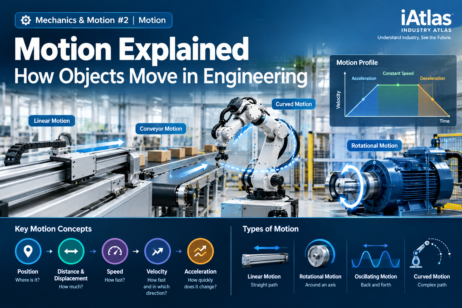
Types of Motion in Engineering
Industrial equipment uses several basic types of motion.
Linear Motion
Linear motion occurs along a straight path.
Examples include:
- Pneumatic cylinders
- Linear actuators
- Conveyor systems
- Machine-tool axes
- Sliding stages
A piston moving inside a cylinder is a common example of linear motion.
Rotational Motion
Rotational motion occurs around an axis.
Examples include:
- Motor shafts
- Pumps
- Fans
- Gears
- Spindles
- Wheels
Rotational motion may be described using quantities such as:
- Angular position
- Angular velocity
- Rotational speed
- RPM
We will explore rotational motion and torque later in the Mechanics & Motion learning path.
Oscillating Motion
Oscillating motion repeatedly moves back and forth around a reference position.
Examples include:
- Vibrating mechanisms
- Reciprocating equipment
- Springs
- Some pumps
- Mechanical test systems
Oscillation is closely related to later concepts such as vibration, frequency, and resonance.
Curved Motion
Not every machine component follows a straight line or rotates around a single fixed axis.
Robot arms are a good example.
Several joints may rotate simultaneously while the end effector follows a complex curved path through space.
Modern motion-control systems calculate and coordinate these movements continuously.
Motion in Industrial Equipment
Understanding motion in engineering is essential because most industrial equipment depends on controlled movement.
Conveyor Systems
A conveyor system may need to control:
- Speed
- Direction
- Acceleration
- Deceleration
- Stopping position
If acceleration is too aggressive, transported products may slide or become unstable.
If stopping accuracy is poor, downstream processes may become misaligned.
Robot Arms
A robot does not simply move from one point to another.
Its controller must coordinate:
- Joint position
- Joint velocity
- Acceleration
- Path
- Timing
This allows the robot to move smoothly, accurately, and repeatedly.
Linear Stages
Precision equipment frequently uses linear stages.
Examples include:
- Semiconductor inspection systems
- Optical equipment
- Measurement systems
- Laboratory automation
- Precision manufacturing equipment
Depending on the application, positioning requirements may be expressed in:
- mm
- µm
- nm
As precision requirements increase, motion control becomes increasingly important.
Motors
Electric motors create rotational motion.
That motion may be transferred through components such as:
- Shafts
- Couplings
- Gears
- Belts
- Lead screws
A rotating motor can therefore ultimately create either rotational motion or linear motion.
Pneumatic Cylinders
A pneumatic cylinder converts gas pressure into force and linear motion.
A simplified sequence is:
Compressed Gas
↓
Force on Piston
↓
Acceleration
↓
Linear Motion
This shows how the previous lesson on force connects directly to motion.
Motion and Force Are Connected
In the previous lesson, we learned Newton’s second law:
F = m × a
A net force can produce acceleration.
Acceleration changes velocity.
Velocity describes motion.
So the relationship can be simplified as:
Force
↓
Acceleration
↓
Velocity Changes
↓
Motion Changes
This is why Force & Motion form the starting point of the Mechanics & Motion learning path.
Constant Velocity vs Accelerating Motion
These two situations are fundamentally different.
Constant Velocity
If an object moves at:
5 m/s →
and continues at exactly the same velocity:
Acceleration = 0
There is no change in velocity.
Accelerating Motion
If an object’s velocity changes from:
2 m/s
to:
6 m/s
its velocity has changed.
Therefore:
Acceleration ≠ 0
The same is true if only the direction changes.
Motion Profiles in Machines
Industrial machines usually do not start and stop instantaneously.
A typical controlled motion profile may look like this:
Start
↓
Acceleration
↓
Constant Speed
↓
Deceleration
↓
Stop
Why?
Because sudden changes in motion can create:
- High mechanical loads
- Vibration
- Product movement
- Wear
- Positioning errors
Controlling acceleration and deceleration can therefore improve machine performance and reliability.
Industrial Example: Moving a Workpiece
Imagine an automated stage that must move a workpiece:
Travel Distance = 500 mm
with a target speed of:
200 mm/s
The stage cannot realistically jump instantly from:
0 mm/s
to:
200 mm/s
Instead:
- The motor accelerates the stage.
- The stage reaches the target velocity.
- It travels at approximately constant velocity.
- It decelerates near the destination.
- It stops at the required position.
This is a basic motion-control problem.
The engineer may need to consider:
- Travel distance
- Velocity
- Acceleration
- Load
- Position accuracy
- Stopping distance
These parameters are closely connected.
Why Acceleration Matters to Mechanical Design
Acceleration creates a mechanical consequence.
Remember:
F = m × a
Suppose two systems move the same 20 kg load.
Machine A accelerates gradually.
Machine B accelerates very rapidly.
Machine B requires a greater net force to create the higher acceleration.
That can affect:
- Motor requirements
- Structural loads
- Bearings
- Vibration
- Energy demand
- Mechanical life
So motion settings can directly influence mechanical design.
Motion and Precision
In modern industry, motion is not only about moving quickly.
It is often about moving accurately and repeatably.
This is especially important in:
- Semiconductor equipment
- Display manufacturing
- Battery assembly
- Precision inspection
- Robotics
- Automated laboratories
A machine axis may need to reach a commanded position repeatedly with extremely small deviation.
This leads to concepts such as:
- Accuracy
- Precision
- Repeatability
- Resolution
These concepts will later be explored in the Measurement & Control category.
A Simple Way to Analyze Motion
Whenever you see movement in an engineering system, ask:
- Where does it start?
- Where does it end?
- How far does it travel?
- How fast does it move?
- Which direction does it move?
- Does its velocity change?
- How quickly does it accelerate or stop?
These questions provide a useful framework for understanding the motion of many machines.
Key Takeaway
Motion in engineering describes how an object’s position changes over time.
Engineers use several concepts to describe it:
Position
↓
Distance & Displacement
↓
Speed & Velocity
↓
Acceleration
Motion can be:
- Linear
- Rotational
- Oscillating
- Curved
And because force can create acceleration, force and motion are fundamentally connected.
Force changes motion by creating acceleration.
Understanding motion is the next step toward understanding how machines convert forces into useful mechanical movement.
Engineering Fundamentals Learning Path
Previous Lesson
⚙️ Mechanics & Motion #1 | Force & Motion → What Is Force in Engineering?
Force Explained: What Is Force in Engineering?
Learn how force, mass, acceleration, net force, and newtons explain the behavior of machines, structures, and industrial systems.
Current Lesson
⚙️ Mechanics & Motion #2 | Motion → Position, Speed, Velocity & Acceleration
Motion Explained: How Objects Move in Engineering
Understand how engineers describe the movement of machines using position, displacement, speed, velocity, and acceleration.
Next Lesson
⚙️ Mechanics & Motion #3 | Work → How Force Transfers Energy
Work Explained: What Does Work Mean in Engineering?
Learn why force alone does not necessarily mean work is being done, how distance matters, and how mechanical work connects force to energy.
References
- OpenStax — Position, Displacement, and Average Velocity
Reference material covering position, displacement, distance, velocity, and reference frames. - OpenStax — Acceleration
Explains acceleration as the rate of change of velocity and the relationship between velocity, direction, and time. - NASA Glenn Research Center — Newton’s Laws of Motion
Educational material covering motion, velocity, acceleration, and their relationship with force.
ℹ️ About iAtlas
iAtlas is an independent publication covering batteries, semiconductors, OLED, advanced materials, AI, and global industrial trends.
We transform complex industrial developments into clear, reliable, and easy-to-understand insights.
Whether you’re following today’s industry news or building long-term expertise, iAtlas helps you understand not only what happened, but why it matters.
Technology creates change.
Insight creates opportunity.
— iAtlas